

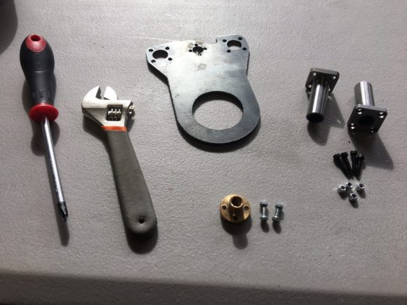
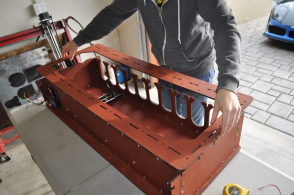
The slider and actuator assembly of the robotic bartender is perhaps the most critical piece. What device is responsible for moving your glass, pouring your ingredients, and delivering your final cocktail. After your frame is constructed (and customized) it’s time to move on to internal components. See below how SirMixABot is put together. Even if your bot comes pre-assembled, it can be interesting to look at the inner workings.
Step 1: Attach the Lower-Slider Plate to the lower space and Rail Holder
- Locate the lower-slider plate. You’ll need to align and stack several pieces (shown from bottom to top).
- The SBR 12 linear bearings
- The Lower Spacer and Belt Holder
- The Lower Slider Plate
- The Lower Vertical Rail Holder
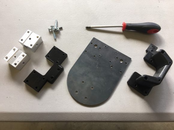
- Locate the lower spacer and belt holder. For this piece, there is a rectangular groove where the drive belt sits. This rectangular groove should be facing up.
- Stack the SBR 12 bearing, then the lower spacer, then the slider plate, then the Lower Vertical Rail Holder. All 8 bolt holes should be aligned.
- Finally, attach directly to the SBR12 linear bearings using 4 M5 x 35mm bolts. Do not TIGHTEN we still need to insert the belt assembly.
Step 2: Attach and Tighten the Belt Assembly onto the Sliding Assembly.
- We’ve provided “excess” amount of the GT2 timing belt. Measure out a total of 85” in length (or 42.5” once the belt is “looped”). Keep the remainder of the belt overlapping.
- You can use tape to hold this loop of belt in place
- Place the overlapped-belt area in the slot of the lower-spacer
- Now you can proceed to tighen the 4 M5 x 35mm bolts that hold the “Stack” together
- You can further tighten the belt in place using the M5 x 10 set screws (these should be firm, but not over tightened)
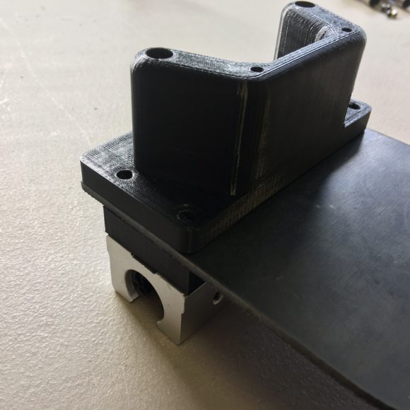
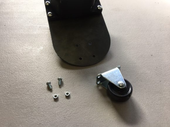
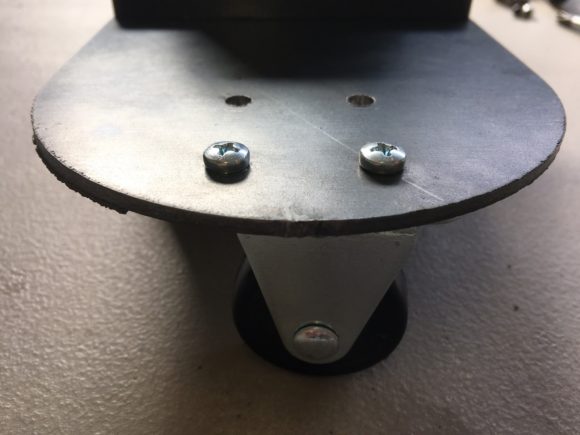
Step 3: Attach the sliding wheel to the Lower-Slider Plate
- Using the M4 x 12mm bolts and nuts [CHECK] attach the sliding wheel to the front of the steel plate.
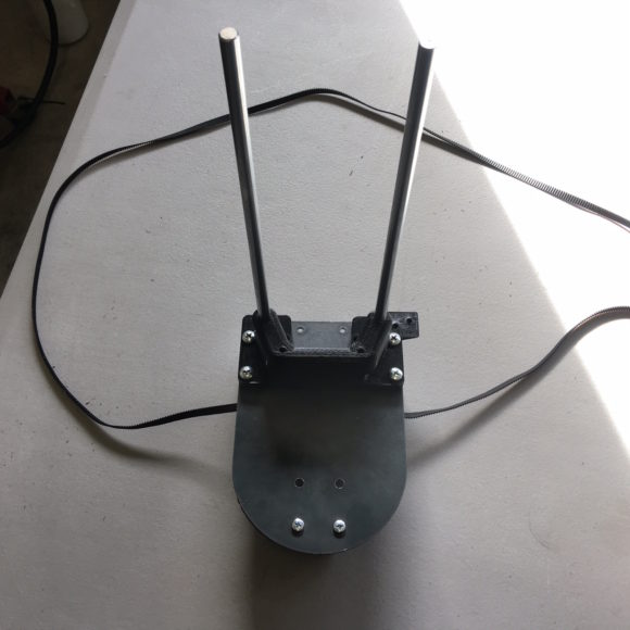
Step 4: Attach the Rail Guides into the lower slider assembly
- Locate the two 8mm guide-shafts.
- The fitment to the plastic is meant to be a tight fit (tolerance fit) so several steps MAY be required:
- With some light tapping, the shafts should enter the
- If that light tapping seems to be excessive, you can ream the holes using [#CHRIS CORRECT] Drill bit then attempt the fitting again.
- Ensure the 8mm Shafts reach the bottom (they should hit the plastic spacer)
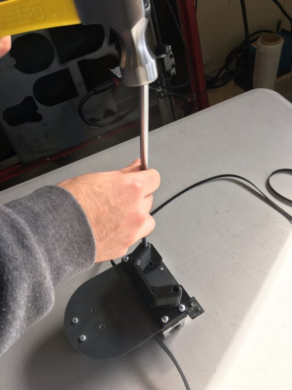
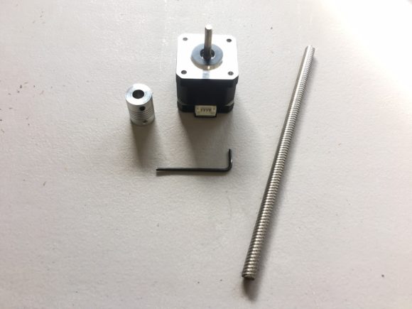
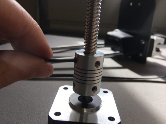
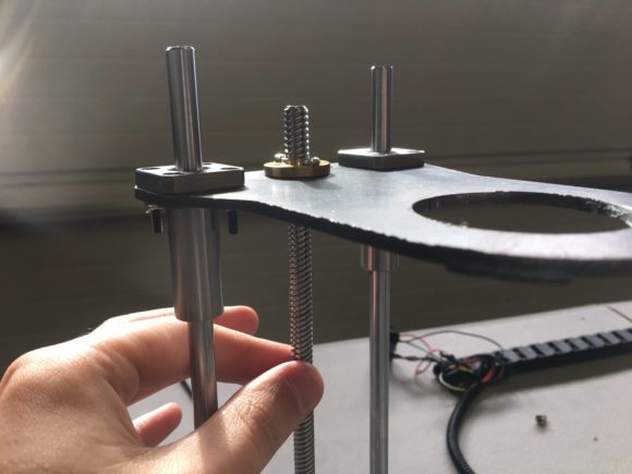
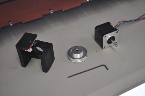
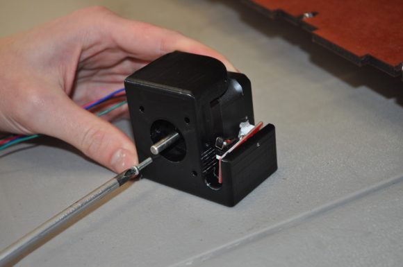
Step 5: Attach Flex Coupling and Threaded Rod
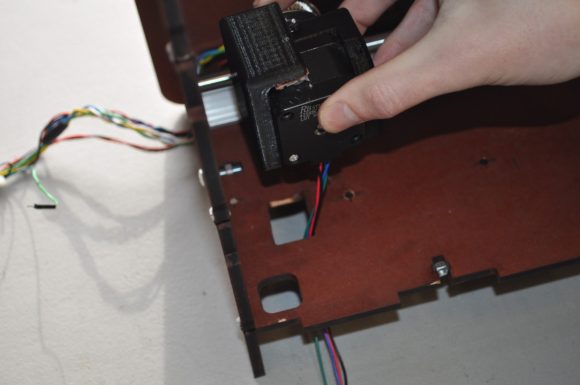
- Locate the NEMA-17 stepper motor, Aluminum Flex Coupling, and Threaded Guide Rod shown below:
- Attach the flex coupling to the Stepper Motor, then slide the threaded Rod into the flex coupling. Be sure to loosen the set-screws (4) using an Allen Key Wrench first.
- Ideally position the flex coupling so that 50% of the stepper shaft is inside, and other 50% is threaded guide rod then tighten all four (4) set screws.
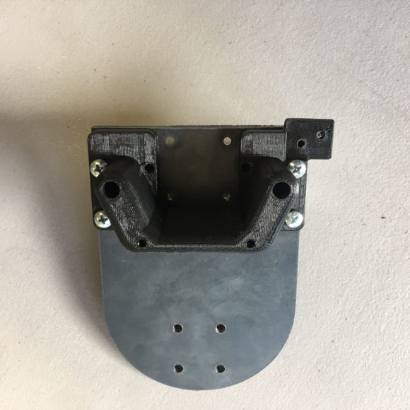
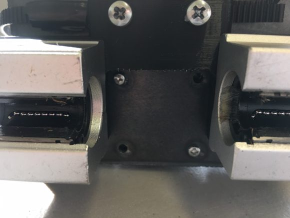
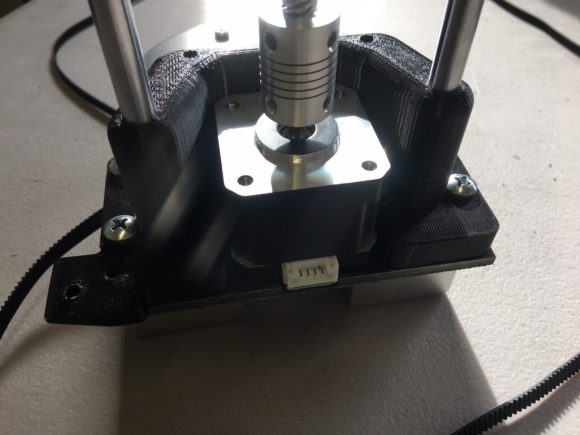
Step 6: Attach the Stepper Assembly to Lower Slider Assembly
- Now locate the M4 screws that came with the robotic bartender kit. These screws will be used to attach the stepper + threaded rod assembly to the lower-slider assembly.
- Flip the lower-slider assembly on its side then place the stepper such that the cable-connection protrudes from the rear.
- Attach the 4 M4 screws from the bottom of the lower plate as shown below:
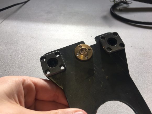
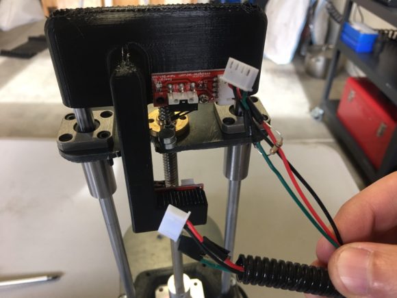
Step 7: Attach the drive nut to the Upper Drink Actuator:
- Locate 2 M3 x 12mm bolts to attach the upper brass drive nut to the steel upper drink actuator
- Attach the brass drive nut from the top, and then insert the two M3 bolts and secure with M3 nuts.
- Note: These clearances are EXTREMELY tight, so we normally place 2 bolts at the front and back rather than side by side.
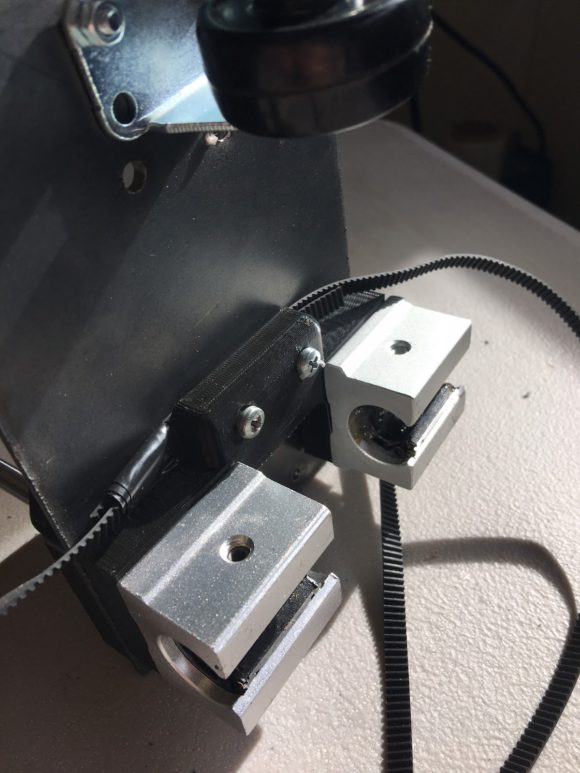
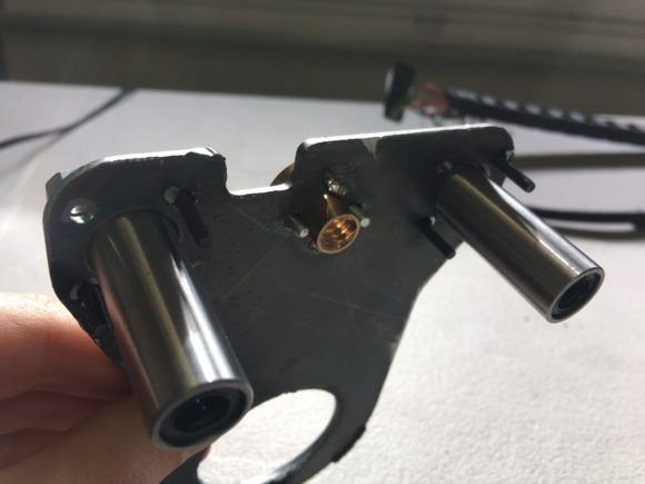
Step 8: Attach the 8mm Linear Bearing to the Upper Drink Actuator.
- Locate 8 M3 x 12mm bolts and corresponding nuts to attach the 8MM Linear Bearings to upper drink actuator.
- Insert the 8mm Linear Bearings to align with the pre-cut holes, then place bolts into the assembly and tighten the nuts.
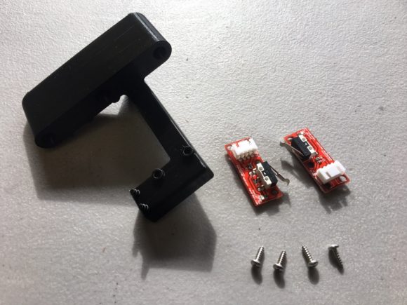
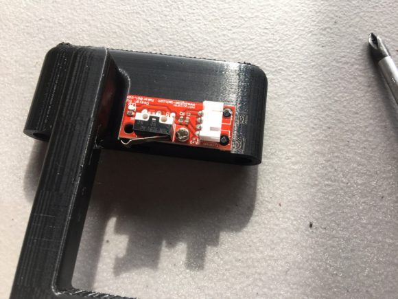
Step 9: Attach the upper limit switch to the Upper Rail Hold
- Locate one of the three limit switches used in the Robotic Bartender, as well as the Upper Rail Holder and 1 #4 x ⅜” sheet metal screw.
- On the back side of the rail guide use the aligned holes and two protruding “nubs” to locate the limit switch onto the Upper Rail Holder
- Use the provided #4 screw to secure the limit switch. (Note only the center screw can be mounted given that otherwise it would interfere with the threaded rod)
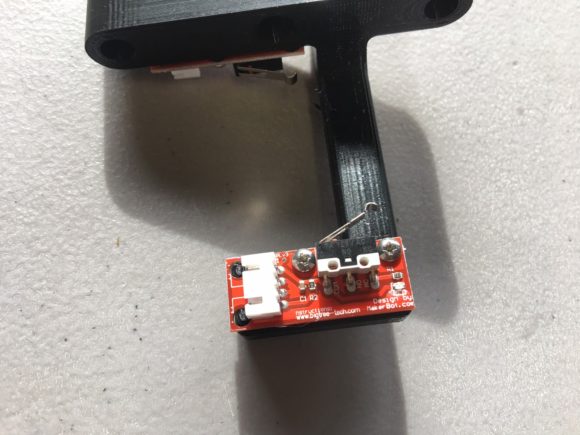
Step 10: Attach the lower limit switch to the Upper Rail Hold
- Locate one of the three limit switches used in the Robotic Bartender, as well as the Upper Rail Holder and 21 #4 x ⅜” sheet metal screw.
- On the front lower side of the rail guide use the aligned holes and two protruding “nubs” to locate the limit switch onto the Upper Rail Holder
- Use the provided #4 screws (2 of them this time) to secure the limit switch.
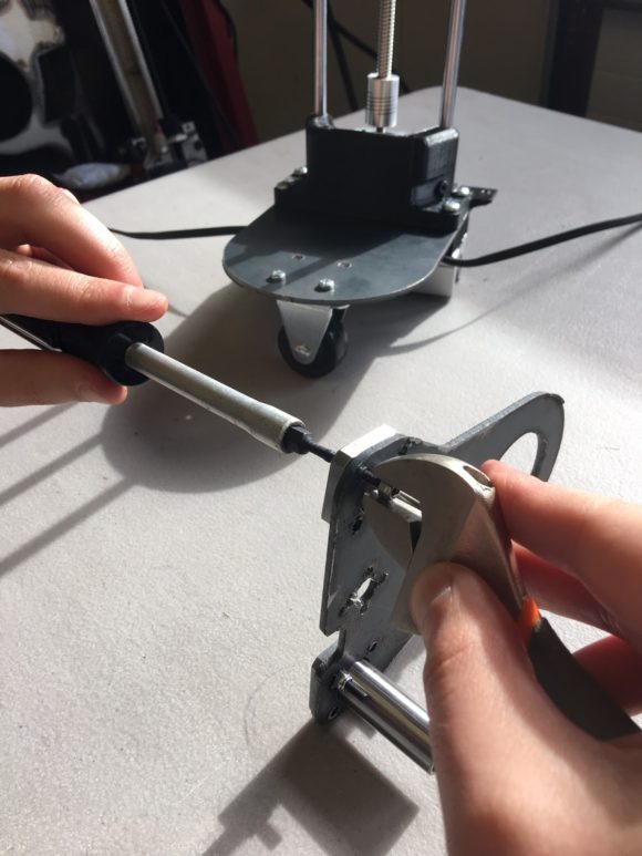
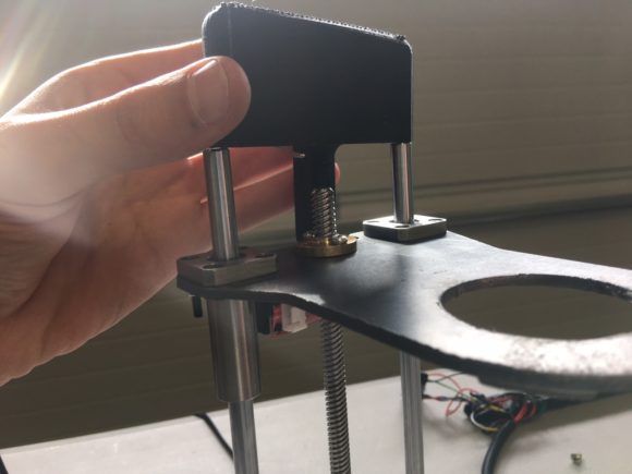
Step 11: Slide on the upper drink actuator assembly:
- Now that you’ve got three assemblies (lower drink slider, upper drink actuator, and upper rail holders) we’re going to attach them all
- Slide the upper-drink actuator (using the linear bearings as guides) over the two 8mm rails.
- Now that the 8mm rails are aligned with the linear bearings, turn the threaded rod assembly through the brass upper drive nut. Turn the threaded rod so about 1” protrudes from the top as shown below.
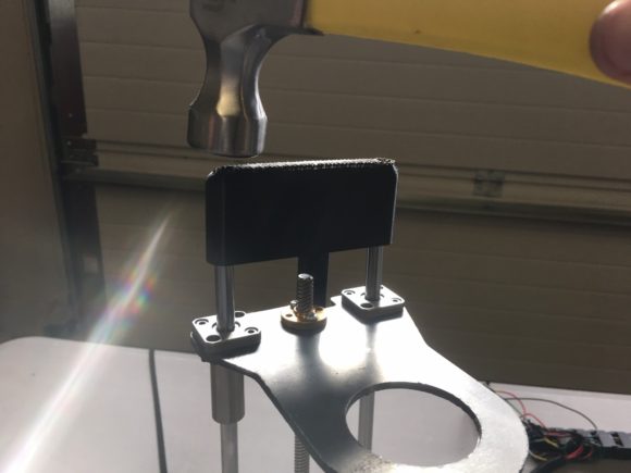
Step 12: Attach the Upper Rail Holders
- Much like the lower rail holders, this upper rail holder is press-fit over the 8mm rails.
- With some light tapping, the shafts should enter into the assembly
- If that light tapping seems to be excessive, you can ream the holes using a drill bit then attempt the fitting again.
- The assembly needs to be tapped down so the total distance between the lower-sliding plate and the bottom of the upper rail holder is the correct fit.
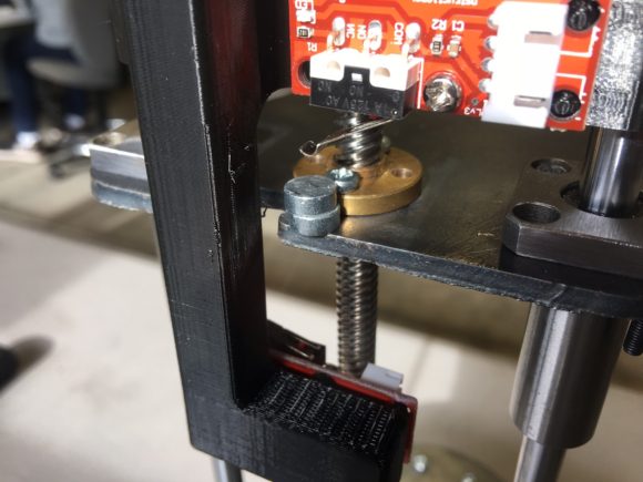
Step 13: Attach two magnets to the back of the drink actuator for limit switch actuation
- When we get Sir Mix A Bot up and running, we’ll need to tune the exact position that a drink dispenses.
- To make sure the lower plate moves far enough to make contact with the upper limit switches we attach two magnets just below the limit switch arm as shown below (On the top rear side of the upper drink actuator).
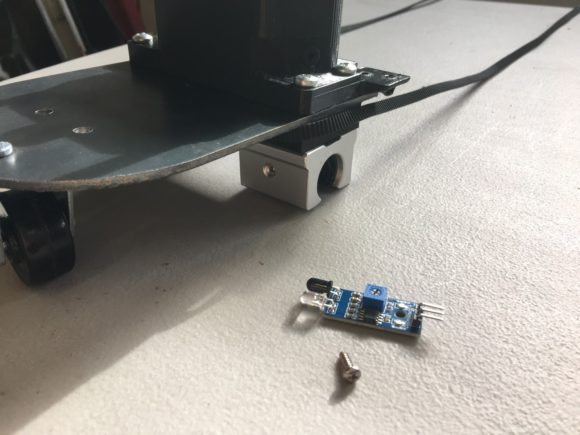
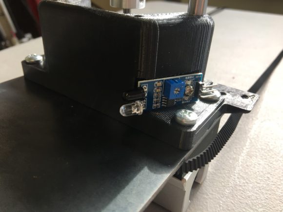
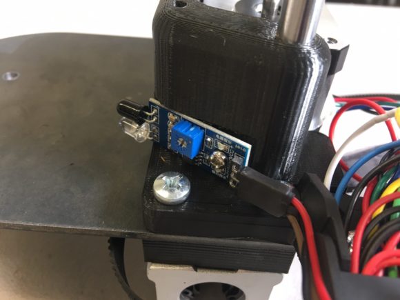
Step 14: Attach the IR sensor to lower rail mounts:
- Locate the infrared sensor and 1 #4 x ⅜” sheet metal screw. This sensor is used to detect whether a cup is present on the tray.
- On the bottom rail holder, there’s a cutout for this sensor with an included pre-made hole. Use a philips head drive to attach the IR sensor using the middle hole.
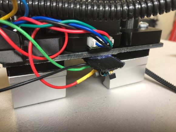
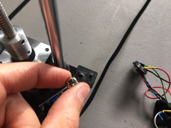
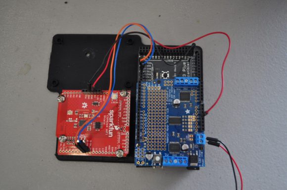
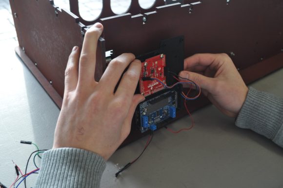
Step 15: Mount the Hall Sensor (carefully!)
- This is a very important step! The Hall sensor is the device that let’s the robotic bartender know when it’s at the right position. It may require some tuning to get right but the goal is to align the hall sensor exactly centered to the sliding drink assembly AND a very small distance to the magnets.
- In order to properly mount the hall sensor, you’ll need a bit of hot-glue to get the appropriate mounting point.
- In addition, you’ll mount the wiring harness which comes pre-filled in with the Hall Sensor in a Female 3-connector outlet with resistor.
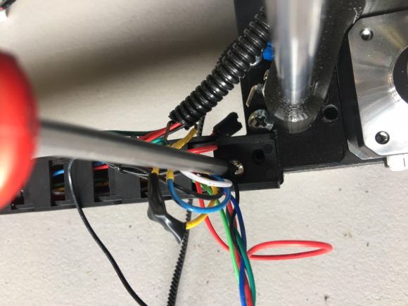
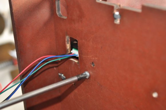
Step 16: Slide the wiring harness through the Drag Chain
- You’ve been provided with a main harness. One end of this harness has to go through the drag chain and mount to the Arduino controller.
- Since most cable are braided, it can be tedious by sliding them through just requires some wiggling and patience.
Step 17: Drag Chain to the Lower Rail Holder
- With the full harness available, mount one of the drag Chain on the lower-rail holder
- This requires two #4 screws and should align with the holes on the 3d printed mount
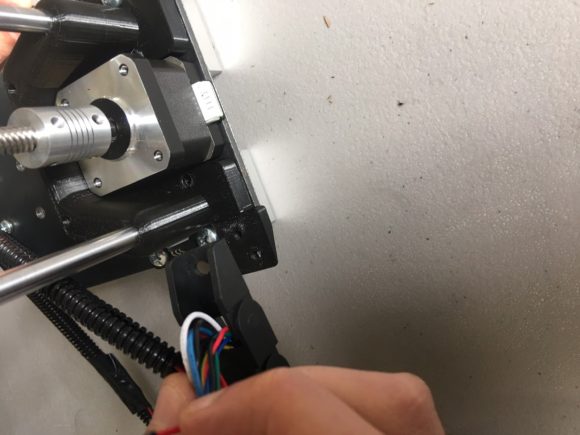
Step 18: Connect the Limit Switches to the Harness:
- Locate the wiring loom cover (~300mm) and two square shaped connections that connect to the limit switches
- Snap the connections in place noting that the harness that leads to the BLUE wire is the bottom limit switch, and the harness that connects to the YELLOW wire is the upper limit switch.
Step 19: Connect the IR Sensor:
- Locate the female connector with the RED/BLACK/WHITE wires. These connect to the analog IR sensor
- The RED wire connects at the TOP of the IR sensor, which is labeled VCC on the IR sensor itself.
SPECIAL NOTE: The IR sensor is meant to detect whether a cup is present. The philips screw can be tuned to detect the right distance/sensitivity of the sensor itself, but you can easily bypass the sensor if you’re in a location with a lot of IR noise (e.g. in direct sunlight). Look for the green LED light to be always on when the sensor is detecting IR.
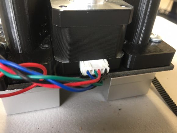
Step 20: Connect the Stepper Motor to the wiring Harness.
- Finally – plug in the stepper motor to the harness:
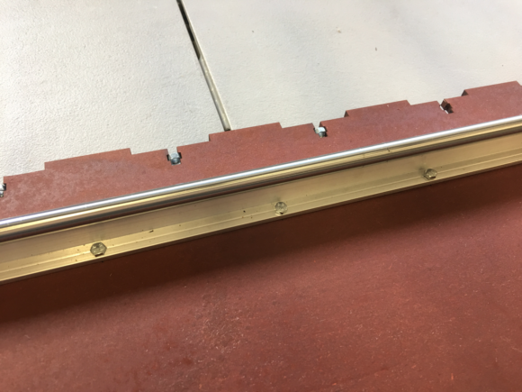
Step 21: Slide the rail onto the sliding rail assembly
- Now it’s time to take the 1098mm rail, and slide it into the rail assembly.
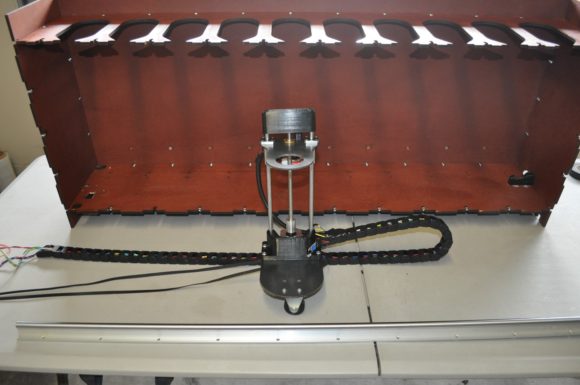
Step 22: Mount the Rail Assembly to the frame of the robotic bartender
- Taking the entire assembly and 22 of the provided bolts and nuts, attach the lower rail to the frame.
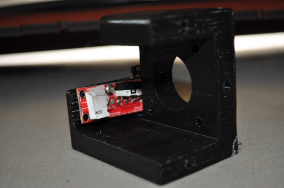
Step 23: Assemble the X axis Stepper Motor Mount to its Limit Switch
- Locate the stepper motor X axis mount and the final limit switch.
- Using the #4 x ⅜” screw, bolt the limit switch to the motor mount. Note that two large “protrusions” should help keep the rear of the limit switch from rotating.
Step 24: Attach the Stepper Motor to the Mount
- Locate the second NEMA 17 stepper motor. Identify the 4 Phillips head screws on the back of the device and remove (2) of them completely.
- Align the 4 front-facing holes and bolt the stepper to the mount
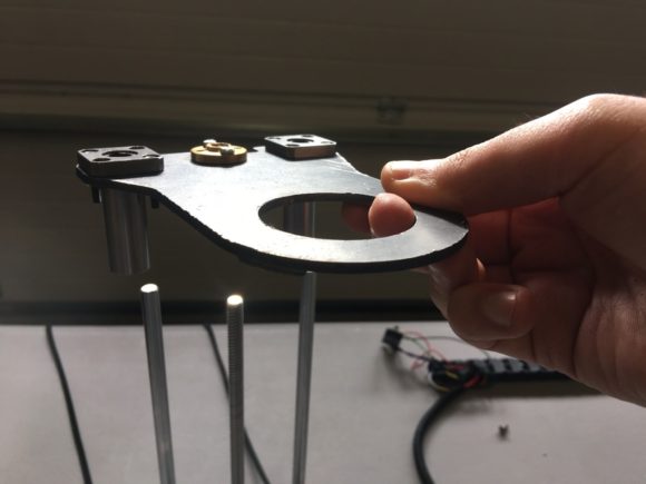
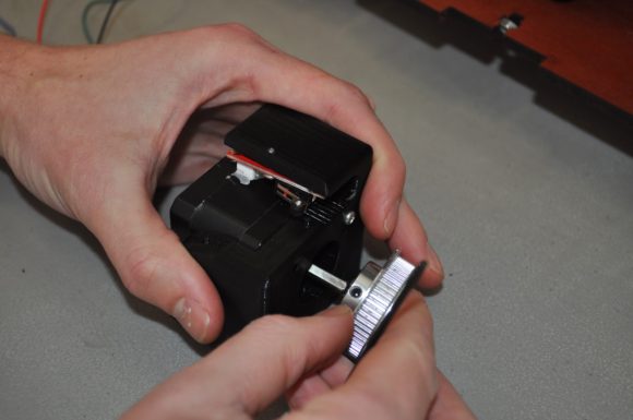
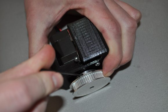
Step 25: Attach front-pulley to the Stepper Motor
- Now with the stepper motor attached, locate the large 65T pulley, and using a slide onto the stepper motor shaft.
- Be sure to align at least one of the set-screws with the flat portion of the stepper shaft.
- Using about an 6mm (¼”) Gap from the plastic frame, tighten the set screws using a small allen wrench.
Step 26: Mount the Stepper Motor to the Birch Frame.
- Using (3) of the #4 x ¾” screws, locate the mounting holes for the final stepper motor.
- Align the 3d printed frame over these 3 plastic holes, then bolt down.
- Be careful to slide the wiring harness through the pre-cut slot created in the birch frame.
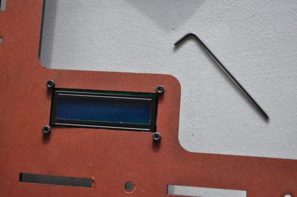
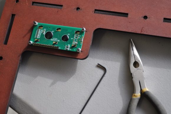
Step 27: Mount the I2C LCD Screen to the front of the birch frame.
- Before bolting on the birch frame, locate the I2C and hex head M3 bolts.
- Using 4 M3 bolts and nuts, attached the LCD screen to the frame.
Step 28: Mount and assemble the birch frame front
- Position the LCD screen on the left side of the frame.
- Snap the slots into place (some light tapping may be needed for fitment)
- Bolt the M5 x 20 bolts to secure the frame front
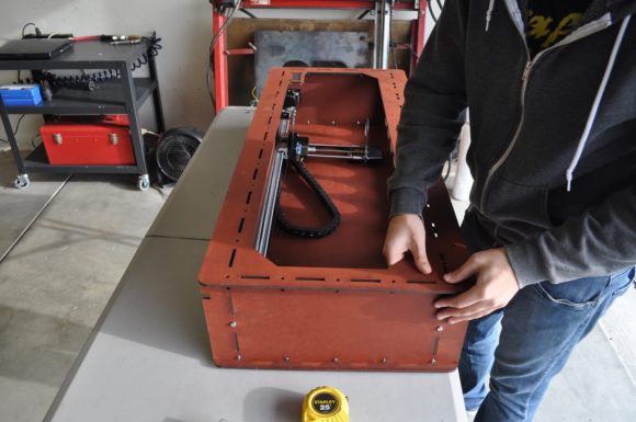
Step 29: Mount the electronic to the electronic tray mounts
- Locate the Arduino 2560, Motor Controller Board, ESP8266 Board, and Buck Converter. These components will all be mounted on the electronic tray mount using the provided #4 x ⅜” screws.
Step 30: Mount the electronic mount to the bottom of the frame
- Locate the flat-printed electronics mount. This will mount to the bottom of the birch frame using supplied bolts and nuts.
- Its easiest to Flip the assembly on its side for the initial mounting and NOTE: The image below shows the tray being mounted with electronics in it (but it’s easier not to have the electronic attached).
Next Steps: Final Wiring
And with that, all the major components of the SirMixABot robotic bartender are in place! At first glance it feels like a lot of components go into the product. However, after assembling you can see that it isn’t too complicated. Everything is designed with longevity, affordability, and customization in mind. The final step is to complete the wiring for SirMixABot. Rest assured, the majority of the work is behind you. Those empty glasses will be filled soon!